Table of Contents
Features
- Interfaces with the MindWave Mobile with an Arduino board via BlueSMiRF Silver module
- Acquiring the Attention and Meditation eSense values from the data stream.
- Displaying your Attention level using LEDs
Introduction
This step-by-step guide is intended to quickly get a typical Arduino board user up and running with the MindWave Mobile. This guide will show how to setup the BlueSMiRF Silver quickly for communication with the MindWave Mobile and gives example code to parse the output stream. The parsed output stream can then be used to perform various tasks such as to control the speed of a motor, to light up LEDs, and to control the position of a servo motor, etc.
Required Materials
This application requires the following materials:
- MindWave Mobile
- Arduino Diecimila was used to develop (please see the note below if you are using a Mega 2560 or Uno)
- BlueSMiRF Silver/Gold, https://www.sparkfun.com/products/10269
- Arduino development environment
- Avago HDSP-4832 10-Element LED bar graph array
- 4 75Ω resistors
- 6 47Ω resistors
- Breadboard
- 12V Power Source (included with Arduino Board)
- Bluetooth dongle, if your computer does not have internal bluetooth capabilities
System Overview
The system uses the Aduino's hardware UART for both USB communication and Bluetooth communication.
The basic setup flow is as follows:
- Pair the MindWave Mobile to your computer to determine the MAC address
- Connecting the BlueSMiRF to your Arduino board
- Pair the BlueSMiRF to your computer to configure the device
- Connect the LED array to the Arduino board.
- Download the provided example code into the Arduino board using the Arduino development environment.
- Power up the whole system and observe the Attention eSense value on the LED array.
Detailed Instructions
Determining the MAC address of your MindWave Mobile
- Open Bluetooth Settings on your computer, and click “Add a Device” or “New Connection”
- To make the MindWave Mobile discoverable, power on the headset. Once the LED turns on, hold the power switch up for 4-5 seconds, until the LED begins to double-blink. It is now discoverable.
- Pair the MindWave Mobile, and determine it's MAC address, which is a 12 digit hexadecimal value
- Write this down, we will use this value later
Connecting the BlueSMiRF to your Arduino Board
You can solder headers to the BlueSMiRF module, and then use jumper wires to connect to the Arduino board. I soldered wires directly to the BlueSMiRF. Either method will work.
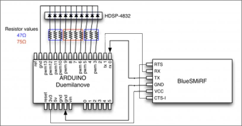
- Short RTS and CTS together. I soldered a wire between the RTS and CTS.
- Connect BlueSMiRF Vcc to Arduino's 3v3.
- Connect BlueSMiRF GND to Arduino GND
- Connect BlueSMiRF TX to Arduino RX
- Connect BlueSMiRF RX to Arduino TX
Powering the Arduino
The Arduino may be powered by USB, by battery, or by an external power supply. Please see the Arduino hardware page here http://arduino.cc/en/Main/Hardware for more information.
Configuring your BlueSMiRF Module
- Once you power up your Arduino board and have the BlueSMiRF connected, you will see a red LED blink on your BlueSMiRF module.
- Pair the BlueSMiRF to your computer. It will appear, as similar to, RN-42-5922.
- The Default Baud Rate is 115200
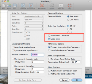
- Open your Terminal Software, and connect the BlueSMiRF. The LED will turn green when it's connected.
- This may take a few tries. You can power cycle the Arduino if you experience issues.
- To put the BlueSMiRF into COMMAND mode, type $$$. Please reference this website: http://www.sparkfun.com/datasheets/Wireless/Bluetooth/rn-bluetooth-um.pdf
- If successful, you will see “CMD”
- Type: D
- You will see the current configuration of the BlueSMiRF.
- Now type: SP,0000
- This will change the pincode from '1234' to '0000'
- Now type: SM,3
- This will configure the BlueSMiRF to Auto-Connect Mode. Once the module is powered up, it will immediately look to connect.
- You should see “AOK” if this is done properly.
- Now type: SR,MAC ADDRESS
- Insert the 12 digit address you copied from the MindWave Mobile.
- Again, look for AOK.
- Now type: SU,57.6
- This will change the BaudRate from 115200 to 57600
- Type: D
- Check to be sure that the stored address is the Mac address, and it's configure to Auto, not Slave
- Type: — (three minus signs)
- This will exit out of Coolterm. If successful, you will see END.
Checking BlueSMiRF configuration
- Power on your MindWave Mobile headset
- Power on your Arduino + BlueSMiRF board.
- If the BlueSMiRF LED turns green, and the MindWave Mobile LED turns solid blue, you are now connected and receiving data from the MindWave Mobile.
- If not, please retry to configure your BlueSMiRF or check the proper MAC address/
Note for Arduino Mega 2560 and Arduino Uno Users
Do not attach the BlueSMiRF Rx / Arduino Tx connection. This will cause a communication bug.
Circuit Schematic
Sample Code
Running the Sample Code
- Once you have synced the program and your board, disconnect the TX and RX lines coming out of the Arduino
- File > Upload to I/O Board
- Once the program displays “Done Uploading”, you can disconnect the USB serial port and run the Arduino from independent power source.
- Reconnect TX and RX lines.
- Power up the Arduino Board via power source
- Arduino should have green PWR LED lit and dongle should have red LED lit
- Turn on Mindwave Mobile Headset
- Hit “Reset” button to pair the MindWave to the dongle.
- Once connected MindWave Mobile LED will turn blue and BlueSMiRF will turn green.
- Enjoy observing your Attention eSense value on the LED array.
Getting started with the Arduino development environment
Please see Arduino Getting Started guide here http://arduino.cc/en/Guide/HomePage
Arduino Code Description
Arduino code is based on the C/C++ language and requires very little else to get started. All the details or regular microprocessor development such as processor clock speed, programming speed, clock sources, etc. are all initialized by the Arduino core. With this in mind, the Arduino system will still be able to perform much of the required tasks with no problem at all. The simplicity of using the microprocessor peripherals combined with the C language along with the sample code provided provides for very quick interface to the MindSet. The user is encouraged to extend the Arduino code by appending code after the indicated section where the packet has been checked for a valid checksum.
Thereafter, the user may use the eSense values to do one of many things possible. Some of which is to control the brightness of an LED, the height of an object, etc.
The bulk of the code is used for parsing the packet data. For further information, see the MindSet Communication Protocol document in the MindSet Development tools (MDT). The MDT is available at the NeuroSky Store for free. http://store.neurosky.com
Material Sources
The Level Converter and Arduino board can be obtained from:
Sparkfun Electronics
6175 Longbow Drive,
Suite 200
Boulder, CO 80301
http://www.sparkfun.com
More information about the Arduino can be found here: http://www.arduino.cc

